Adaptive feedback
feedforward compensation for disturbance rejection in a one DOF flexible
structure: comparative analysis
Compensación
adaptativa feedback feedforward para el rechazo de perturbaciones en una
estructura flexible de un grado de libertad: análisis comparativo
Efraín Mariotte1, Jabid
Quiroga2, Silvia Oviedo3
1Escuela de Ingeniería Mecánica,
Universidad Pontificia Bolivariana, Bucaramanga, Colombia. Email:
efrain.mariotte@correo.uis.edu.co
2Escuela de Ingeniería Mecánica,
Universidad Industrial de Santander, Bucaramanga, Colombia. Email: jabib@uis.edu.co
Institut
d’Informàtica i Aplicacions, Universitat de Girona, Girona, España.
ABSTRACT
In this paper an Active Vibrational Control (AVC) for a
three-cart problem is studied. The Filtered-x Least Mean Square (FxLMS) and
Recursive Least Square (RLS) algorithms are compared in terms of disturbance
rejection, computational cost and control effort when a correlated measurement
of the disturbance is available. The proposed RLS compensator considers a
feedback coupling between the compensator and the disturbance. The secondary
propagation path of the plant was estimated using normalized LMS (NLMS)
algorithm. The internal positive coupling is modeled as a FIR filter estimated
by the real plant parameters. Simulations showed a superior performance of RLS
algorithm with a reasonable computer cost. The comparative analysis was
performed comparing the tradeoff between the filter order and the magnitude of
the rejection.
KEYWORDS: Index terms –active vibration control; fir
adaptive filter; the filtered-x least mean square; recursive least square.
RESUMEN
En este artículo se estudia un Control Vibratorio
Activo (AVC) para un problema de tres carritos. Se comparan los algoritmos de
mínimos cuadrados filtrados (FxLMS) y mínimos cuadrados recurrentes (RLS) en
términos de rechazo de perturbaciones, costo computacional y esfuerzo de
control cuando se dispone de una medición correlacionada de la perturbación. El
compensador RLS propuesto considera un acoplamiento de retroalimentación entre
el compensador y la perturbación. La ruta de propagación secundaria de la
planta se estimó utilizando el algoritmo LMS normalizado (NLMS). El
acoplamiento positivo interno se modela como un filtro FIR estimado por los
parámetros reales de la planta. Las simulaciones mostraron un rendimiento
superior del algoritmo RLS con un costo informático razonable. El análisis comparativo
se realizó comparando la compensación entre el orden del filtro y la magnitud
del rechazo.
PALABRAS
CLAVE: Términos del
índice -active vibration control; fir filtro adaptativo; el cuadrado medio
menos filtrado de x; recursive least square.
INTRODUCTION
Nowadays, the research in Active Vibration Control (AVC) is
gaining importance because of the increase in the number of electro-mechanic
devices working in high speed applications. AVC uses an electromechanical or electroacoustic
system, which cancels out the unwanted vibrations based on the superposition of
wave’s principle.
The adaptive controller scheme used is the Self Tuning
Regulator (STR), in which the estimate of the process parameters is updated and
the controller parameters are obtained from the solution of a design problem
using the estimated parameters. The Adaptive Controller can be thought of as
being composed of two loops, the inner loop consists of the process and an
ordinary feedback controller, the parameters of the controller are adjusted by
the outer loop which is composed of a recursive parameter estimator and a
design calculation.
Meanwhile, Active Disturbance Rejection Control (ADRC) is a
robust control method based on extension of the system model with an additional
fictitious state variable, representing the uncertainties present in the
description of the plant.
This study was conducted through the "Young
Researchers" program of Colciencias as part of a research project entitled
"Comparative study of nonlinear techniques AVC infinite H-adaptive filter
for a flexible structure whit one degree of freedom". The adaptive
approach (STR), using RLS and LMS algorithms, are used both as a mechanism to
estimate in real time the plant parameters and as a mechanism to adjust
controller parameters. LMS (Least Mean Squares) algorithm represents the
simplest and most easily applied adaptive algorithm while RLS (Recursive Least
Squares) algorithm represents increased complexity, increased computational cost
but faster convergence. Additionally, RLS algorithm approaches the Kalman
filter performance in adaptive filtering applications at somewhat reduced
throughput in the signal processor.
In the study of the additive feedback coupling between the
compensator and the disturbance measurement, was concluded that the absence of
this feedback propagation path causes an error due to lack of synchronization
with the actual response simulation in the adaptive control [1].
On the other hand, this feedback coupling may destabilize
the system because of the lag between the simulation feedback compensation and
the disturbance in its additive correlation. The simultaneous use of both an
adaptive feedback compensator and a feedforward compensation to reject the
disturbance is proposed [2], where it is stated that the action of the feedback
loop adds a new design specification for the stability conditions to the
adaptive feedforward compensation.
The differences in implementation between the Digital Signal
Processing (DSP) broadband feedforward control and the adaptive feedback
control and its application schemes in AVC are well studied in the literature
[4-5], also the adaptive sinusoidal disturbance rejection in linear discrete
time systems.
Least Square and regression models commonly used in Active
Noise Control (ANC) to model without using conventional simplifying assumption
regarding the physical plant to be controlled are the Filtered-X LMS (FxLMS)
and RLS due to its simplicity in calculation and Digital Signal Processing
(DSP) implementation to adaptive filtering in contrast to the result in system
identification [6-11].
In this work a feedforward adaptive compensator is proposed,
considering the feedback coupling in the disturbance rejection problem for a
three-cart model. First, the propagation paths are fully identified as a group
of transfer functions in series. The propagation paths are NLMS-based estimated
as FIR filters. The adaptive compensation filters with RLS and FxLMS algorithms
are applied for disturbance rejection in the studied plant.
THREE CART DYNAMICS WITH INERTIAL ACTUATOR
Figures 1 and 2 represent an AVC test bed in which the
vibration measurement is correlated with the disturbance and an inertial
actuator is used for reducing the residual acceleration. The system consists of
five metallic plates connected by springs. The plates M1 and M3
are equipped with inertial actuators. M1 serves as disturbance
generator (inertial actuator 1 in Figure 2) and M3 serves for
disturbance compensation (inertial actuator 2 in Figure 2). The system is
equipped with a measure of the residual acceleration (on plate M2)
and a measure of the disturbance signal by an accelerometer on plate M1.
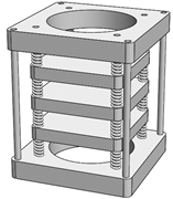
Figure 1. Studied plant model, AVC system. Source: authors.
In the described scheme, the path between the disturbance
(in this case, generated by the inertial actuator on the top of the structure),
and the residual acceleration is called the global primary path. The
path between the position of M1 (an image of the disturbance) and
the residual acceleration (in open loop) is called the primary path and
the path between the inertial actuator used for compensation and the residual
acceleration is called the secondary path. When the compensator system
is active, the actuator not only acts upon the residual acceleration, but also
upon the measurement of the disturbance image (a positive feedback).
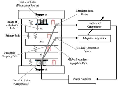
1. Figure 2. Scheme of the plant, AVC system. Source:
authors.
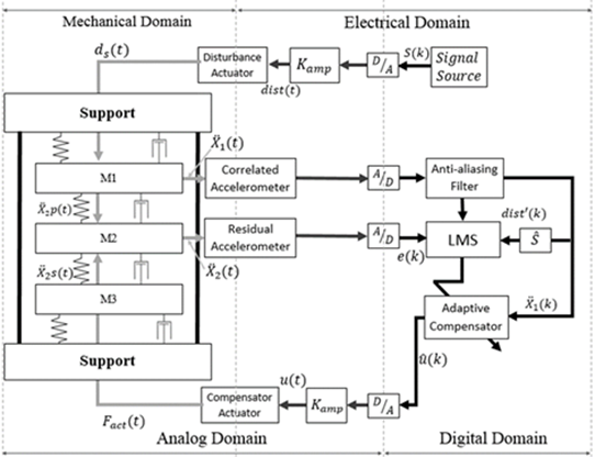
The disturbance is the pressure wave of the inertial
actuator (see Figures 1 and 2) located on top of the structure. The output of
the compensator system is the pressure wave of the inertial actuator located on
the bottom of the structure. The parameters of the filter are estimated to
minimize the measurement of the residual acceleration. In Figure 3 it can be
observed the block diagram of the AVC system. The  filter
emulates the band limiter filter and the speaker. The disturbance source is
white noise filtered by to
obtain
filter
emulates the band limiter filter and the speaker. The disturbance source is
white noise filtered by to
obtain . The filter
  emulates
the global primary path which contains the disturbance and the mechanical path
between the pressure wave and the residual acceleration. The filter
emulates
the global primary path which contains the disturbance and the mechanical path
between the pressure wave and the residual acceleration. The filter  characterizes
the dynamics of the disturbance source and the image of the disturbance
(inertial actuator + dynamics of the mechanical system). The compensation
actuator is modeled by the transfer function Act with the control
signal as input and the pressure wave as output (power amplifier + the
compensation inertial actuator).
characterizes
the dynamics of the disturbance source and the image of the disturbance
(inertial actuator + dynamics of the mechanical system). The compensation
actuator is modeled by the transfer function Act with the control
signal as input and the pressure wave as output (power amplifier + the
compensation inertial actuator).
The secondary path is represented by the  block (see Figure
3(a)), which models the dynamics of the pressure wave traveling from the
inertial compensator actuator to the residual acceleration in the absence of
the disturbance. The Fc block emulates the
mechanical path between the compensation inertial actuator and the correlated
disturbance. The feedforward compensator is the
block (see Figure
3(a)), which models the dynamics of the pressure wave traveling from the
inertial compensator actuator to the residual acceleration in the absence of
the disturbance. The Fc block emulates the
mechanical path between the compensation inertial actuator and the correlated
disturbance. The feedforward compensator is the  block
with
block
with  as
the correlated noise and the residual acceleration (the desired signal) as
inputs and the output
as
the correlated noise and the residual acceleration (the desired signal) as
inputs and the output  as
the control signal. The value of
as
the control signal. The value of is the
sum of the correlated disturbance measurement
is the
sum of the correlated disturbance measurement  obtained
in the absence of the feedforward compensation (see Figureure 3(a)) and the
effect of the actuator used for compensation.
obtained
in the absence of the feedforward compensation (see Figureure 3(a)) and the
effect of the actuator used for compensation.
Figure 3. Block diagram of the plant of the AVC system a)
open loop b) with the feedforward compensator. Source: authors.
SYSTEM IDENTIFICATION OF THE PROPAGATION PATHS
A System identification process is implemented to estimate
the impulse response of the four propagation paths in the AVC system. The
obtained models consider the un-modeled dynamics inherent to the simplification
of the plant. The system is modeled using an Adaptive Filter with
Normalized LMS algorithm (NLMS) to adapt the impulse response of the Unknown
System (Nominal plant + uncertainties + the measurement error) injecting
band limited noise to both i.e. the Adaptive Identification System and
the Unknown System and comparing their response, see Figure.
Figure 4. Secondary path Identification Using the NLMS
Adaptive Filter. Source: authors.
Each propagation path is fully identified and emulated as a FIR filter using
the coefficients of the adaptive filters. The FIR filter obtained for the
secondary path has a response time of 10
ms and its identification
process is illustrated in Figure. 5.
Figure 5. Secondary path Identification Using the NLMS
Adaptive Filter. Source: authors.
Figure 6 shows the behavior of the estimated secondary path impulse response
and the comparison with the estimated path. The performance in the estimation
of the impulse response of the adaptive filter in the tail is poor but does not
affect the operation of the studied AVC system in a significant way.
Primary Propagation and Feedback Coupling Propagation Paths
identification
Figure 6. Secondary path Impulse response
identification. Source: authors.
The primary propagation path Pc is modeled by
a linear filter. This filter is obtained in absence of compensation and
observing the signal of the accelerometer, which measures the correlation
signal, after an impulse disturbance is applied by the disturbance actuator.
The coefficients of the FIR impulse response filter represent the response of
the entire global primary path.
The system identification of the propagation path of the
“Additive” Feedback Coupling is the measure of the effect of the inertial
actuator compensation over the correlated accelerometers in the absence of
disturbance.
AVC USING FILTERED-X LMS FIR ADAPTIVE FILTER
In the design of the FIR adaptive filter using the
filtered-x-LMS algorithm the additive feedback coupling was not considered. In
Figure. 7 a) the scheme of the proposed plant and in 7 b) the block diagram of
the same plant, it can be observed that the correlated noise is the measure of
the image of the perturbation, and
the desired signal is . The
digital adaptive compensator is a feedforward controller of 500th
order and step size of 0.01.
. The
digital adaptive compensator is a feedforward controller of 500th
order and step size of 0.01.
The experiments were carried out by first applying the
disturbance in open loop during 30 s and then closing the loop with the
adaptive feedforward-feedback algorithms. The band limited disturbance source
emulates the bandwidth attribute to the vibration of rotating machinery, that
are generally the primary source of vibrations in industry.
a)
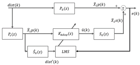
Figure 7. Schematic arrangement of feedforward AVC system
with FxLMS b) Block Diagram. Source: authors.
Figure 8 shows the resulting power spectral density of the
residual acceleration, where Channel 1line corresponds to the residual
accelerometer without compensation and Channel 2 line is the residual
acceleration with compensation.
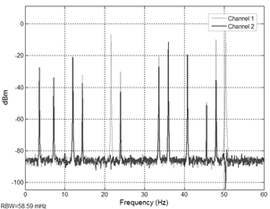
Figure 8. Power spectral of AVC of the Filtered-x LMS.
Source: authors.
In the same Figure, Channel 2 exhibits frequencies of 21Hz
and 50 Hz (the higher components of the disturbance) which are attenuated below
-40 dB. On the other hand, it is also observed a decrease in the compensation
performance at components 34 Hz and 36 Hz, which are partially ignored by the
compensator generating the maximum amplitude value of the error signal. Time
domain signal obtained in open loop and with the compensator (using adaptive
feedforward compensation algorithm FxLMS) on the AVC system are shown in
Figure. 9. The residual acceleration, in channel 2, is quantified as the
variance of the residual force (error) on the mass 2. The compensator provides
a mean reduction of 26.40 dB in the acceleration of the controlled mass.
ADAPTIVE FEEDFORWARD AVC USING RLS ALGORITHM WITH FEEDBACK COUPLING
A new control scheme is proposed to accomplish disturbance
rejection in order to improve the performance observed in the feedforward
FxLMS. This new compensator considers the feedback coupling caused by the
compensator actuator affecting the correlated disturbance shown in Figure 3.
The design process of the compensator using the RLS
algorithm shown in Figure 3, resulted in 70th order FIR Filter. The
performance of the new control scheme can be appreciated in Figure 10-11. In
Figure 10 the frequency response of the residual acceleration with and without
compensation in Channel 2 and Channel 1 is presented, respectively. In Figure
11, Channel 1 signal is the disturbance applied to the plant and Channel 2
signal corresponds to the residual acceleration on mass 2.
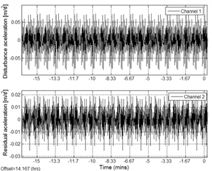
Figure 9. Disturbance rejection of the feedback Filtered-x
LMS. Source: authors.
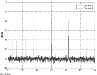
Figure 10. Spectrum of the frequency response of AVC using
RLS algorithm with feedback coupling. Source: authors.
When using only adaptive feedforward compensation RLS the
mean disturbance reduction is 39.2 dB. Clearly, RLS scheme brings a significant
improvement in performance with respect to the other schemes offering in
addition adaptation capabilities with respect to the disturbance
characteristics.
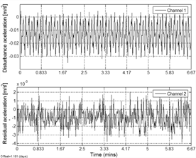
Figure 11. Disturbance rejection of the AVC using RLS
algorithm with feedback coupling. Source: authors.
2. ADAPTIVE FEEDBACK AVC USING FXLMS ALGORITHM
The Figure 12 a) shows the schema of the Adaptive Feedback
AVC System using the FxLMS algorithm and 12 b) the block diagram. The system
produces its own reference signal using an estimated path, the adaptive filter
output and the error signal. The main advantage of this scheme is the use of
only one accelerometer. The reference signal or primary noise is expressed in
Z-Domain as:
 (1)
(1)
Where  is
the estimated secondary propagation path,
is
the estimated secondary propagation path,  is
the error signal and
is
the error signal and  is
the secondary signal produce by the adaptive filter.
is
the secondary signal produce by the adaptive filter.
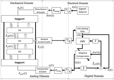
Figure 12. a) Schematic arrangement of feedback AVC system
with FxLMS b) Block Diagram. Source: authors.
The resulting 500th order filtered-XLMS uses the
conventional LMS algorithm. Comparing Figure 11 and Figure 13 it can be noted a
decrease in performance of the compensation when the adaptive feedback using
FxLMS is implemented. The lack of compensation performance is attributed to the
system identification process because although the correlation between the
desired signal and the correlated signal is 1 the system was incapable to fully
identified specific values of frequencies.
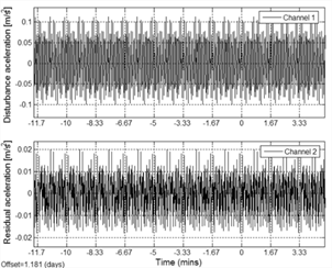
Figure 13. Disturbance rejection of the AVC using feedback
FxLMS. Source: authors.
Figure 14 shows the frequency spectrum of the closed-loop
system, the peaks with the high amplitude to be attenuated at 21 Hz and 50 Hz
can be observed in the Channel 1. Comparing Figure. 10 with Figure 14 it can be
observed the lower performance in disturbance rejection of the feedback FxLMS
AVC system compared with the feedforward compensators. This lack of performance
is the result of an additional computational cost associated to the calculation
of the reference disturbance signal. Additionally, in the generation of the
reference signal some frequencies of the desired signal are attenuated by the
filters that emulate the propagation path so the compensator misses out attenuated
signals in the calculation. The mean disturbance reduction is (20dB), when the
feedback controller is active.
Table 1. Comparative performance board
|
AVC Filter
|
Filter order
|
Attenuation (dB)
|
|
FxLMS in feedforward
|
500
|
26,40
|
|
RLS in feedforward
|
70
|
39,2
|
|
FxLMS in feedback
|
500
|
20
|
Source: Own elaboration.
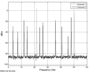
Figure 14. Power spectral of the AVC system using feedback
FxLMS. Source: authors.
CONCLUSIONS
In this paper three different designs of the adaptive filter
with FxLMS and RLS as adaptive algorithm were applied to periodical disturbance
rejection in an AVC system. Simulations show that the implementation of the
FxLMS feedforward AVC System uses a reasonable amount of effort to find the
opposite form of the disturbance compared with feedback FxLMS. The compensation
using the FxLMS feedforward scheme was unable to fully identify all frequency
components to be attenuated in the residual acceleration. This poor performance
can be attributed to the high computational cost associated with the adaptation
algorithm.
The implementation of the feedforward AVC system with RLS
algorithm considering the feedback coupling shows better results in the
attenuation of the disturbance, with a moderate size for the adaptive filter.
Tests reveal instability when the unappropriated adaptation step is chosen. The
instability is attributed to the positive feedback.
The feedback coupling provides a best estimation of the
plant model compared with estimated secondary path filters obtained by NLMS.
Simulations demonstrate a better disturbance rejection and low computational
cost using the feedforward AVC system with RLS algorithm.
REFERENCES
[1] I. D. Landau, M. Alma, J. J. Martinez, and G. Buche,
“Adaptive Suppression of Multiple Time-Varying Unknown Vibrations Using an Inertial
Actuator,” IEEE Trans. Control Syst. Technol., vol. 19, no. 6, pp.
1327–1338, Nov. 2011.
[2] M. Alma, I. D. Landau, J. J. Martinez, and T.-B.
Airimitoaie, “Hybrid adaptive feedforward-feedback compensation algorithms for
active vibration control systems”, IEEE Conference on Decision and Control
and European Control Conference. 2011, pp. 6771–6776.
[3] S. M. Kuo and D. R. Morgan, “Review of DSP algorithms
for active noise control,” in IEEE Conference on Control Applications -
Proceedings, 2000, vol. 1, pp. 243–248.
[4] F. Ben Amara, P. T. Kabamba, and A. G. Ulsoy, “Adaptive
sinusoidal disturbance rejection in linear discrete-time systems - Part I:
Theory,” J. Dyn. Syst. Meas. Control. Trans. ASME, vol. 121, no. 4, pp.
648–654, 1999.
[5] F. Ben Amara, P. T. Kabamba, and A. G. Ulsoy, “Adaptive
sinusoidal disturbance rejection in linear discrete-time systems - Part II:
Experiments”, J. Dyn. Syst. Meas. Control. Trans. ASME, vol. 121, no. 4,
pp. 655–659, 1999.
[6] I. T. Ardekani and W. H. Abdulla, “Stochastic modeling and analysis of
filtered-x least-mean-square adaptation algorithm,” IET Signal Process.,
vol. 7, no. 6, pp. 486–496, Aug. 2013.
[7] I. T. Ardekani and W. H. Abdulla, “Theoretical framework
for stochastic modeling of FxLMS-based active noise control dynamics,” in 2012
Conference Handbook - Asia-Pacific Signal and Information Processing
Association Annual Summit and Conference, APSIPA ASC 2012, 2012.
[8] “DSP System Toolbox TM Getting Started Guide
R 2014 a,” 2014.
[9] T. Wang and W. S. Gan, “Stochastic analysis of
FXLMS-based internal model control feedback active noise control systems”, Signal
Processing, vol. 101, pp. 121–133, Aug. 2014.
[10] S. Liu, D. Liu, J. Zhang, and Y. Zeng, “Extraction of
fetal electrocardiogram using recursive least squares and normalized least mean
squares algorithms,” in 2011 3rd International Conference on Advanced
Computer Control, 2011, pp. 333–336.
[11] L. Lara, J. Brito, C. Graciano, “Structural control
strategies based on magnetorheological dampers managed using artificial neural
networks and fuzzy logic,” Rev.UIS Ing., vol. 16, no. 2, pp. 227 -242,
2017. Doi: https://doi.org/10.18273/revuin.v16n2-2017021